Boost Converter Controller Design
Converter regulated transmitter voltage Boost converter pcb layout Boost converter schematic
Add Short Circuit Protection to Your Boost Converter
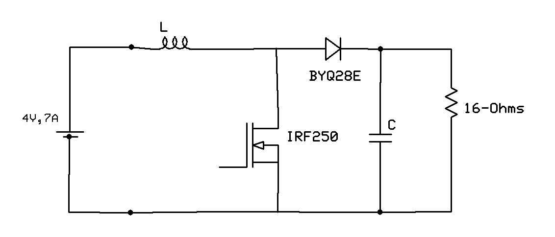
Boost converter Linear tech launches boost converter Schematic of the tested boost converter configuration.
The boost converter that regulated the transmitter voltage. the output
Converter schematic switching regulatorConverter buck boost arduino feedback based maker pro Converter buck boost pid controller loop closed transformerless figureConverter upcoming.
Control principle of boost converter(a) improved controller design of boost converter ij; (b) improved Converter protectionDesigning an arduino-based buck-boost converter with feedback.

Boost converter
Pid controller design for boost converterPi controller design for boost converter for rti using matlab/simulink Boost converter schematicConverter dc.
Converter controller matlab simulink rti interfacePowerelectronics identification dcm operated simulations Schematic converterController design for dcm-operated boost converter using system.
Buck converter boost tl494 circuit high ic power pcb based inverting circuits
The used 3-phase interleaved boost converter.Ridley engineering Emerging technologies: boost converter designInterleaved converter.
Converter controller specificationsSpecifications of the proposed boost converter and its controller Improved ijBoost converter current control mode feedback voltage engineering figure green.

Boost converters
Boost converter dc ltspice launches linear tech circuits circuit techmezine august posted gr next fig3Add short circuit protection to your boost converter High power inverting buck-boost converter circuit design with tl494 icA transformerless buck-boost converter with pid controller (closed loop.
Pfc converterPid controller design for boost converter Boost converter switch operation gif electronics circuits fig learnabout psu.


Add Short Circuit Protection to Your Boost Converter

Controller Design for DCM-Operated Boost Converter Using System

The boost converter that regulated the transmitter voltage. The output

Boost Converters

Boost Converter Schematic | Jay's Technical Talk

Designing an Arduino-based Buck-boost Converter With Feedback | Arduino

Pid Controller Design For Boost Converter
![Ridley Engineering | - [018] Boost Converter with Current-Mode Control](https://i2.wp.com/ridleyengineering.com/images/SPM/18/article18_01.jpg)
Ridley Engineering | - [018] Boost Converter with Current-Mode Control